The Complete Guide to MC Step Up Transformers (SUT)
MC Step Up Transformers: Introduction
If you own a low output moving coil (MC) phono cartridge or are considering one, you’ve likely come across the term MC Step Up Transformer (SUT).
Despite being a critical component in analog audio for decades, SUTs remain one of the most misunderstood topics. Even with advancements in phono preamps and op-amps, many audiophiles still consider SUTs essential for their ability to deliver musical, dynamic, and low-noise performance.
In this article, we’ll explore everything you need to know about MC step-up transformers: why you might use one, how they work, what the important technical terms mean, and how to choose the correct SUT for your system. By the end, you’ll see why many audiophiles consider an SUT an essential ingredient to getting the best from a low-output moving coil cartridge.
Table of Contents
1 – MC vs MM Cartridges: Why We Need a Transformer
2 – The Anatomy of an MC Step Up Transformer
3 – Turns Ratio, Impedance, and Output Voltage
4 – “Matching” Myths vs. Real Optimization
5 – The Importance of Transformer Quality (Core Materials, Winding Techniques)
6 – Transformer Ringing, and the Power of RC Loading
7 – Recommended Reading & References
1 – MC vs MM Cartridges: Why We Need a Transformer
Moving Magnet Cartridges (MM)
Moving magnet (MM) cartridges typically produce a higher output of around 4–5 mV. Their design features moving magnets that induce voltage in fixed coils, generating a strong enough signal to be directly processed by a standard phono preamplifier.
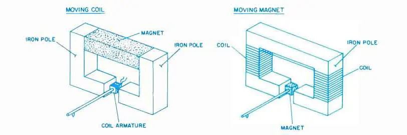
Fig. 1 – Moving Coil vs Moving Magnet Cartridge Designs
Moving Coil Cartridges (MC)
Moving coil (MC) cartridges typically produce a lower output of around 0.2–0.5 mV, though exceptions exist. They use fixed magnets and ultra-light moving coils, making them more responsive than moving magnet designs. However, this refined construction results in a weaker signal that requires additional gain to match the levels expected by a standard MM phono preamplifier.
That extra gain can come from:
1. A MC phono preamp (with enough low-noise gain)
2. A dedicated “head amplifier” (or pre-preamp)
3. A step-up transformer (SUT)
Why choose a step up transformer at all?
Historically, step-up transformers were the best way to get 20–30 dB of clean gain for MC carts.
Modern semiconductor technology has improved, but transformers remain coveted for their low noise and euphonic distortion characteristics (when well-designed). Tube phono stages, in particular, often still need an SUT, because tubes alone struggle to deliver high amplification at very low noise levels.
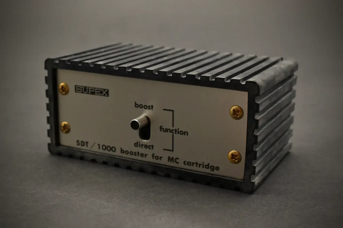
2 – The Anatomy of an MC Step-Up Transformer
An SUT is a passive device: it requires no power supply and draws no current. It consists of three key components:
– Primary Winding: Connects to the MC cartridge and receives the low-voltage signal.
– Secondary Winding: Outputs an amplified signal to the MM phono input.
– Magnetic Core: Made from materials like mu-metal, Permalloy, or amorphous alloys to enhance magnetic flux transfer.
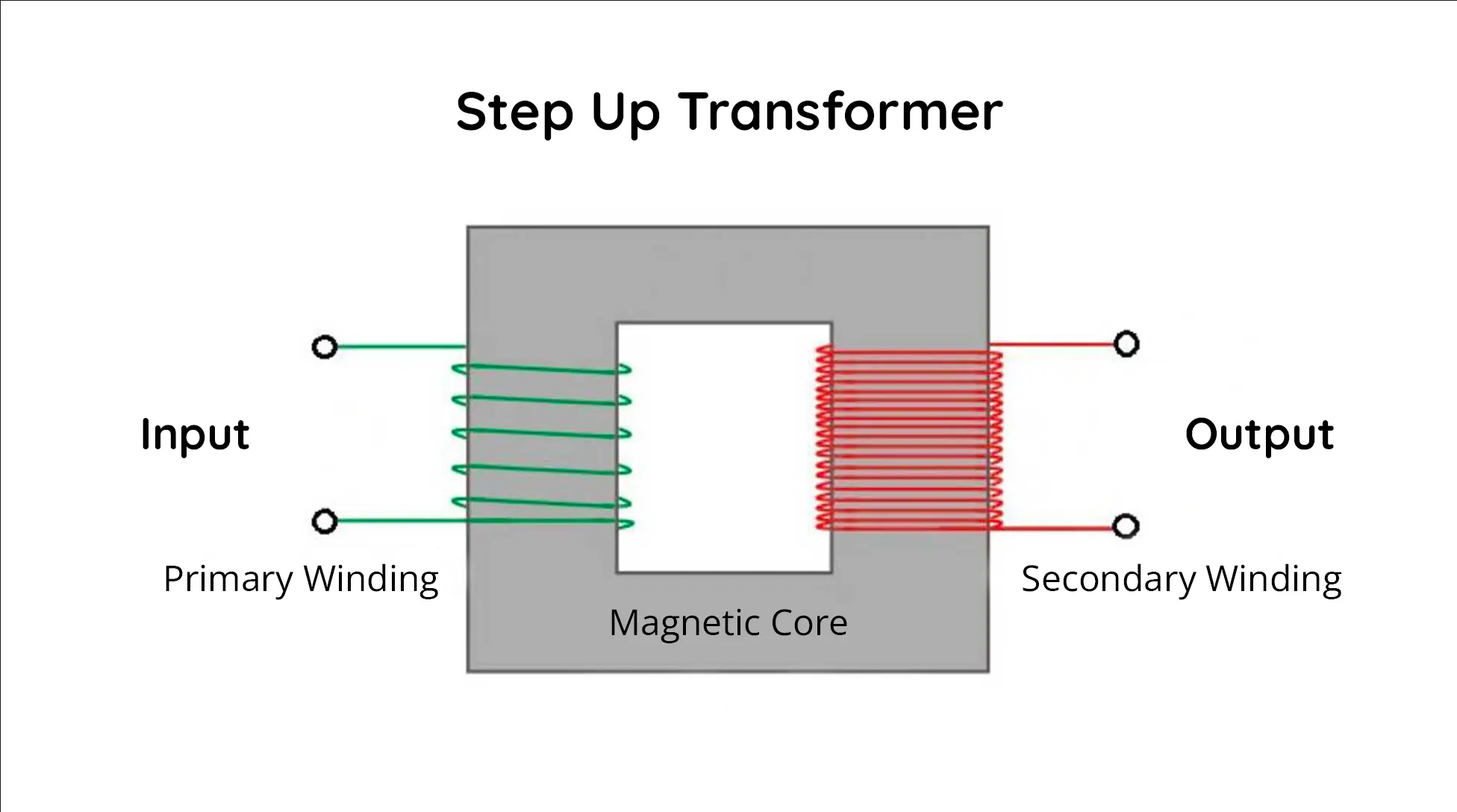
Fig. 2 – MC Step Up Transformer Diagram
When the MC cartridge signal enters the primary winding, the turns ratio between the primary and secondary windings steps up the voltage. This process does not generate power but rather converts low voltage and high current into higher voltage and lower current, ensuring compatibility with an MM phono stage.
3 – Turns Ratio, Impedance, and Output Voltage
Turns Ratio
The turns ratio, a key parameter, defines the relationship between the number of windings on the secondary coil compared to the primary coil. For example, with a 1:10 ratio, an input of 0.5 mV is increased to 5 mV, bringing the signal to the optimal level for an MM phono stage.
Impedance Reflection
Transformers don’t create impedance of their own. Instead, they reflect the secondary load (the standard 47 kΩ MM input) back to the primary according to this formula:
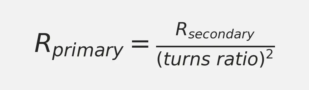
R is impedance in ohms (Ω), and the turns ratio is expressed in “number of times greater”.
For instance, with a 1:10 ratio, the standard 47kΩ MM phono preamp input impedance on the secondary appears as 470Ω at the primary.
Practical Considerations
If your cartridge’s internal impedance is relatively low (~5–10Ω), the 470Ω reflected load is large by comparison, ensuring minimal signal loss and preserving dynamic range.
However, if your cartridge’s coil impedance is high (~40Ω) or the SUT ratio is very high (1:30 or more), the reflected load becomes much lower relative to the cartridge impedance. This configuration restricts current flow, reducing voltage transfer efficiency and causing high-frequency roll-off, leading to a loss of detail and dynamics.
To avoid this, the reflected impedance should generally be at least 5-10 times the cartridge’s internal impedance for optimal performance.
4 – “Matching” Myths vs. Real Optimization
“Matching” Myths
A common misconception is that the cartridge impedance must match the load impedance, meaning the SUT’s primary impedance should equal the cartridge’s internal impedance. While this approach maximizes power transfer according to electrical engineering principles, it is not ideal for this application.
When the SUT’s primary impedance equals the cartridge’s internal impedance, the cartridge “sees” a heavy load, causing excessive current draw. This excessive loading restricts the cartridge’s natural ability to generate voltage, leading to a weaker signal, reduced dynamics, and lower signal-to-noise ratio.
In other words, MC cartridges are voltage generators, not power sources. So our goal is to maximize voltage output, not power transfer. For that, the load impedance should be at least 5–10 times the cartridge’s internal impedance to allow the cartridge to operate freely and produce an undistorted signal.
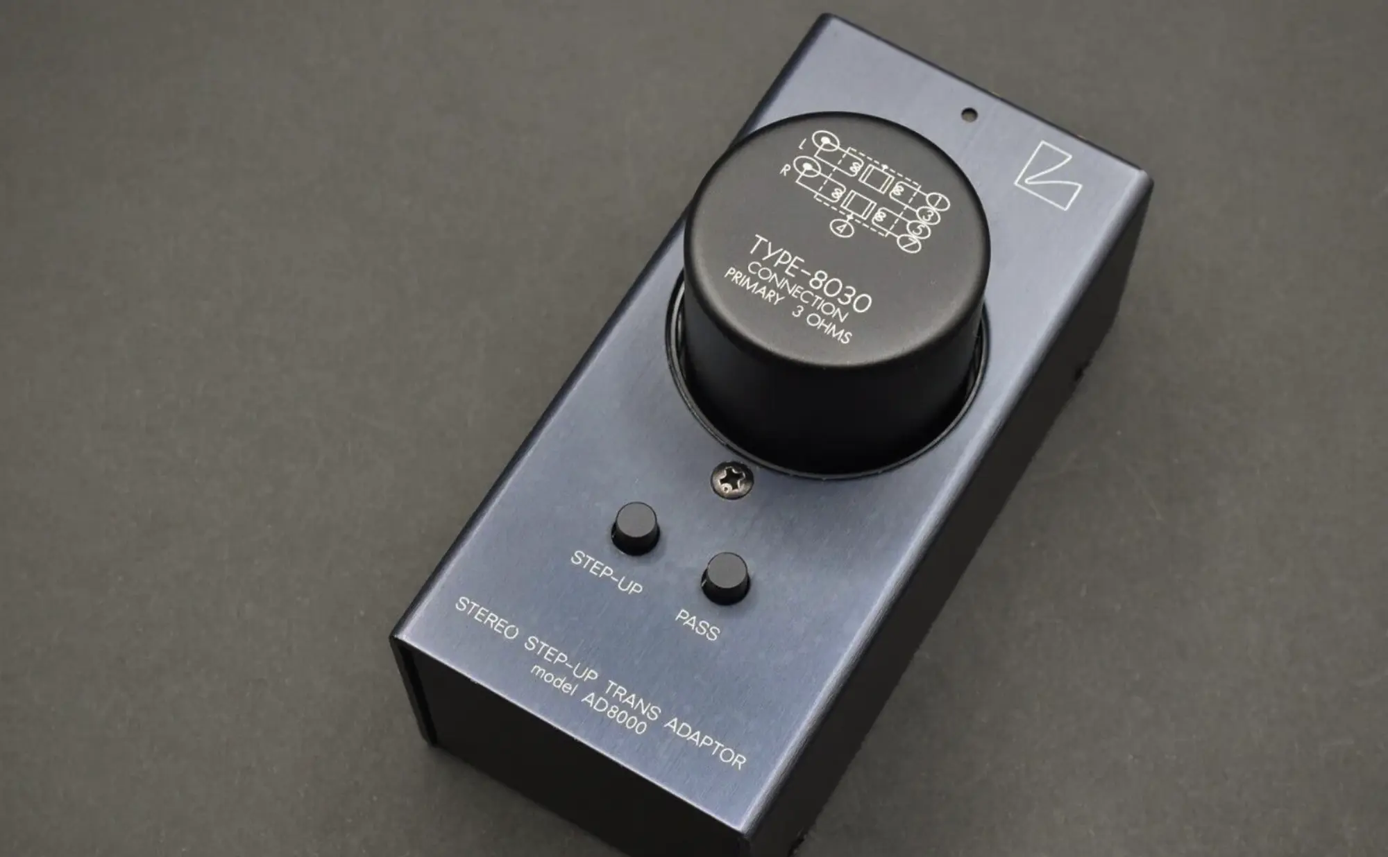
Fig. 3 – Luxman Type-8030 Silver Wire SUT with 1:32 ratio, showing 3 ohms as ideal cartridge impedance
Real Optimization
Achieving optimal results with an MC step-up transformer involves two key considerations:
1. Matching the SUT Output to Your MM Phono Stage
Aim for an output of 4–5 mV for most MM preamps, although you can often go higher depending on the input sensitivity and overload margin of your specific unit.
Modern MM Preamps (Solid-State):
Typically support 2.5–5 mV input sensitivity at 35–45 dB gain, with an overload margin of 50–150 mV. As a result, they can handle 4–6 mV comfortably and sometimes up to 6–8 mV without noticeable distortion.
Vintage MM Preamps (1970s–1980s):
Generally expect 2–3 mV input sensitivity at 30–40 dB gain, with a lower overload margin of 20–50 mV. An SUT output of 3–5 mV is recommended to avoid overloading, especially in tube-based designs that may distort above 8–10 mV.
2. Keeping the Reflected Impedance Within the Ideal Range
Ensure the SUT primary impedance is at least 5–10 times the cartridge’s internal impedance. If the reflected load is too high, the sound may become thin or bright. Conversely, if it’s too low, you can lose clarity and dynamics.
To fine-tune loading, you can add a parallel resistor at the secondary of the SUT. This lowers the total secondary impedance and, by the square of the turns ratio, reduces the reflected impedance at the primary. For instance, with a 1:10 SUT and a default 470Ω reflected load, placing a 17.5kΩ resistor in parallel with the 47kΩ input can reduce the reflected impedance to 200Ω. If you’re unsure about the exact resistor value for your setup, consult our customer support for guidance on the calculations.
5 – The Importance of Transformer Quality (Core Materials, Winding Techniques)
Not all step-up transformers are created equal. Their performance hinges on three primary factors: core material, winding techniques, and shielding. Because an SUT is responsible for handling extremely low-level signals from an MC cartridge, even small design or material flaws can cause audible degradation. Many audiophiles also believe that certain materials impart a particular sonic signature, so there’s a subjective element in choosing the “best” design.
Core Material
The core is essentially the heart of the transformer. Common materials include HiMu 80 (Permalloy/mu-metal), amorphous alloys, and nickel-iron laminations. Permalloy is often praised for its excellent low-frequency response and low distortion, making it a favorite among listeners who value a warm, full-bodied sound. Some audiophiles, however, prefer amorphous alloys for what they describe as a more transparent or detailed presentation, albeit at a higher cost. Nickel-iron laminations can be a middle ground, offering a good balance between bandwidth extension and cost-effectiveness. In practice, personal taste plays a significant role in deciding which core material sounds “best.”
Winding Techniques
In addition to the core, the quality of the windings profoundly affects transformer performance. Factors such as the number of turns, wire gauge, and the spacing between windings determine how efficiently the transformer transfers the cartridge’s tiny signal to the phono stage.
A well-executed winding scheme minimizes leakage inductance and parasitic capacitances, ensuring the transformer can handle a wide frequency range without smearing or rolling off critical high frequencies. In simpler terms, leakage inductance represents unwanted magnetic flux escaping from the primary and secondary coils, while parasitic capacitances form when layers of wire are too close, effectively creating mini-capacitors. Both phenomena can limit bandwidth and cause phase shifts or resonance peaks (“ringing”). Proper winding techniques such as meticulous layering, uniform tension on the wire, and consistent spacing,help keep these effects low, preserving detail, clarity, and dynamics across the entire audible spectrum.
Shielding
Because MC step-up transformers deal with signals in the microvolt range, external noise and interference can easily overshadow the music. Shielding typically involves enclosing the transformer in materials like mu-metal, Permalloy, or copper-coated steel. These shields help block external magnetic fields from nearby power supplies, motors, etc. and maintain a clean signal path.
Some designs use multi-layer shielding, stacking layers of magnetic and conductive materials to capture stray fields more effectively. The goal is to prevent hum, buzz, or radio-frequency interference from polluting the delicate cartridge output. Audiophiles sometimes experiment with additional chassis or grounding techniques to further reduce noise. Ultimately, the success of a shielding strategy depends on both the materials used and how well they’re integrated into the overall design.
6 – Transformer Ringing and the Power of RC Loading
Ringing occurs when a transformer’s inherent inductance and stray capacitances form a resonant circuit that oscillates at high frequencies. This phenomenon may manifest as overshoot or subtle, high-frequency artifacts that can dull transient clarity, particularly noticeable in percussion and string attacks. Although you might not hear a distinct “ring,” the resulting resonance can smear detail and create a harsh or congested sound in the upper registers.
One effective way to mitigate this issue is through RC (Resistor-Capacitor) loading. By placing a small resistor and capacitor (often in series) across the transformer’s secondary winding, the resonant peak that causes ringing is damped. The resistor component absorbs some of the oscillation energy, while the capacitor helps control high-frequency behavior by countering the inductive reactance. When carefully selected and tuned, this RC network preserves the transformer’s overall frequency response and transient accuracy without overloading the cartridge or rolling off the highs.
In essence, proper RC loading allows the transformer to deliver a more natural, balanced sound, free from the subtle distortions introduced by uncontrolled resonance. This is especially important in MC step-up transformers, where any loss of detail at high frequencies can undermine the very qualities that make a moving coil cartridge so appealing: clarity, nuance, and an almost lifelike presentation of instruments and vocals.
MC Step Up Transformers: Conclusion
An MC Step-Up Transformer remains one of the most effective ways to amplify the delicate signals from low-output moving-coil cartridges. By choosing the appropriate turns ratio for your cartridge’s output and ensuring a proper loading network that tames any ringing, you can enjoy music reproduction with stunning clarity, dynamic range, and that elusive “magic” many audiophiles associate with MC cartridges.
It’s important to remember that a well-chosen SUT should balance voltage gain, reflected impedance, and phono stage compatibility to maintain clarity, dynamics, and musicality. Since voltage requirements typically dictate the optimal ratio, modern MC cartridges generally perform best with step-up ratios between 1:10 and 1:20, where the reflected impedance remains high enough to prevent excessive signal loss.
If you found this guide helpful, please share it! This article aims to be a definitive resource on MC Step-Up Transformers. Let’s keep the analog art alive and thriving!
Happy listening!
FREQUENTLY ASKED QUESTIONS
- What kind of Resistor is best for SUT Loading?
- How to Properly Ground my MC Step Up Transformer?
Since the resistor is part of the signal path, resistor quality matters for preserving fidelity. You will find below the best
Metal Film Resistors (Best Value)
– Low noise, low distortion, high precision
– Neutral sound, high stability
– Our Recommendations: Vishay Dale, Takman, PRP
Bulk Foil Resistors (Best Performance)
– Lowest noise and distortion available
– Ultra-high precision (0.005% tolerance)
– Our Recommendations: Vishay Z-Foil, Texas Components TX2575
Avoid Wirewound and Carbon Composition Resistors
– Wirewound resistors introduce inductance, affecting high frequencies
– Carbon composition resistors are outdated, noisy, and unstable over time
Proper grounding is crucial to avoid unwanted hum, buzz, and interference in an MC step-up transformer. Here’s what you need to know:
1. Grounding Basics
- Transformer Shield/Case: Most SUTs come in a metal housing (often mu-metal or Permalloy). Grounding this shield prevents external electromagnetic fields from causing noise.
- Signal Grounds (Unbalanced RCA): In many designs, the primary (cartridge side) and secondary (phono preamp side) share a common ground reference. Some SUTs, however, isolate grounds to reduce hum-inducing ground loops.
2. Unbalanced vs. Balanced Connections
- Unbalanced (RCA): The SUT’s secondary negative typically goes to the phono stage ground, while the primary side references the cartridge ground. If you hear hum, try lifting or reattaching the SUT case ground to see which setup yields the least noise.
- Balanced (XLR): True balanced phono stages may not require the windings to be tied to chassis ground. The SUT shield or enclosure is still grounded to divert external interference, but the cartridge leads remain isolated for a fully balanced signal path.
3. Common Grounding Methods
- Single-Point (Star) Ground: All grounds (SUT, phono preamp, and turntable chassis) meet at one point to minimize loops.
- Separate Chassis Grounding: The SUT’s enclosure is grounded to the phono preamp chassis screw or ground lug, while signal grounds remain separate.
- Floating Grounds: Some designs (especially balanced ones) leave the primary or secondary winding unconnected to ground, helping reduce loops.
4. Troubleshooting Hum
- Test Different Ground Points: Connect or disconnect the SUT’s ground from the chassis or tonearm to find the quietest combination.
- Shielding & Positioning: Keep the SUT away from motors and power transformers.
- Cable Management: Use properly shielded cables and avoid running them parallel to AC power cords.
In Summary:
A properly grounded SUT is vital for clean, noise-free playback. The best approach depends on your system’s design (balanced vs. unbalanced) and the SUT’s grounding scheme. Experimentation is often the simplest way to achieve the quietest, most transparent sound.
Recommended Reading & References
For those looking to dive deeper into MC step-up transformers, you will find here some interesting resources:
Audio Transformers by Bill Whitlock: A technical deep dive into transformer design.
Transformer and Inductor Design Handbook by Colonel Wm. T. McLyman: valuable insights into winding techniques, core materials, and overall design principles.
Join Our Community!
Subscribe to La Newsletter
Stay informed with the latest news and blog posts from the world of high fidelity sound.
Gregory de Richemont
Gregory de Richemont is the founder of Le Son, where high-fidelity sound meets emotional depth. Blending a background in global business with a lifelong passion for analog, Gregory left the corporate world to follow the call of pure sound. His work is dedicated to creating listening experiences that don’t just impress — they move. Learn more on our About Us page.